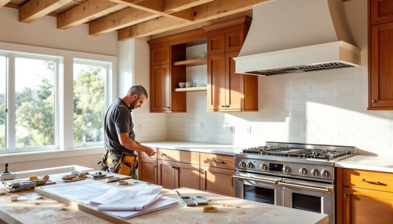

Setting up a home theater without a diagram is like framing a wall without measuring, you’ll get something standing, but it probably won’t be square. A proper setup diagram isn’t just a nice-to-have: it’s the difference between sound that wraps around the viewer and speakers that fight each other, between a clean install and a rat’s nest of cables behind the TV. Whether working with a dedicated basement theater or repurposing a living room, mapping out speaker locations, screen height, seating distance, and wire runs before moving furniture or drilling holes saves time, money, and the frustration of redoing work.
Table of Contents
ToggleKey Takeaways
- A home theater setup diagram prevents costly mistakes by mapping speaker locations, screen height, seating distance, and cable runs before installation, ensuring clean aesthetics and balanced sound.
- Speaker placement follows precise standards: front mains at 22-30 degrees, surrounds at 90-110 degrees, and height speakers in ceiling positions 9-10 feet high for optimal Dolby Atmos performance.
- Subwoofer placement significantly affects bass response—use the crawl method to find the sweet spot, as corner loading amplifies output but can cause boom while midwall positions provide tighter sound.
- Proper wiring diagrams save time and money by calculating cable lengths, gauges, and routing paths upfront; HDMI cables over 15 feet need active or fiber optic models to prevent signal dropout.
- Common installation mistakes like skipping the diagram, ignoring room acoustics, mounting surrounds too low, and undersizing wire paths can be prevented through careful planning and measurement.
- Use tools like SketchUp, Room Sketcher, or laser measuring devices to create accurate room layouts at 1/4-inch scale, documenting permanent fixtures, electrical outlets, and seating positions for a professional home theater setup diagram.
Why a Home Theater Setup Diagram Matters
Most home theater problems stem from poor planning, not cheap gear. Placing a subwoofer in a corner because there’s an outlet nearby, mounting surrounds at eye level because it’s easier, or running HDMI cables alongside electrical wiring creates issues that no amount of receiver calibration can fix.
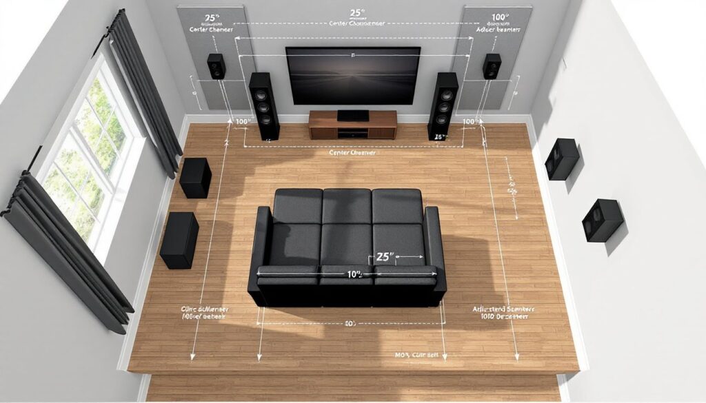
A setup diagram forces decisions upfront: seating distance determines screen size (divide viewing distance in inches by three for diagonal screen size in a dark room, by two for rooms with ambient light). Speaker angles follow standards, front left and right at 22-30 degrees from center, surrounds at 90-110 degrees for 5.1 systems. Subwoofer placement affects bass response: corner placement amplifies output but can cause boom, while midwall positions often sound tighter.
Diagrams also expose practical constraints. That perfect 7.1.4 Dolby Atmos layout might require ceiling access the homeowner doesn’t have. The ideal projector throw distance might put the unit right where a ceiling fan sits. Sketching the room to scale, graph paper works, or free tools like SketchUp, reveals these conflicts before buying equipment or patching drywall.
Permits typically aren’t required for home theater installation unless running new electrical circuits or making structural changes. Local codes vary, but most AV wiring falls outside permit requirements. If adding a dedicated 20-amp circuit for the system or cutting into load-bearing walls for in-wall speakers, check with the local building department first.
Essential Components of Your Home Theater Diagram
A complete diagram maps both equipment and environment. Start with the room dimensions: length, width, ceiling height. Note door swings, windows, HVAC vents, and existing electrical outlets. These aren’t decorative details, they affect everything from screen placement to acoustic treatment.
Display positioning comes next. For TVs, mount height should place the center of the screen at seated eye level, typically 42-48 inches from the floor for standard seating. Projectors require calculating throw distance (distance from lens to screen) and offset (vertical shift). A projector with a 1.5:1 throw ratio needs 15 feet from a 10-foot-wide screen. Mount it too close and the image won’t fill the screen: too far and it dims or goes out of focus.
Seating layout defines everything else. Primary seating should sit at the apex of the speaker triangle. Mark each seat position, noting ear height when seated (usually 36-40 inches). This height determines speaker mounting and aiming points. Secondary seating rows need consideration for surround speakers, speakers aimed at the back row might blast the front row.
Equipment rack or cabinet location goes on the diagram too. AVRs generate heat and need ventilation: stacking them in a closed cabinet without fans causes thermal shutdown. Note rack depth (most AV gear is 16-18 inches deep) and allow 2-3 inches behind for cable management and airflow.
Speaker Placement and Positioning
Front speakers form the foundation. Left and right mains should flank the screen at equal distances, tweeters at ear height. Angle them toward the primary seating position, this is called toe-in and sharpens the stereo image. The center channel sits directly above or below the screen, aimed at seated ear level. If mounting below, tilt it up: above, tilt down.
Surround speakers depend on system configuration. For 5.1 setups, side surrounds mount 2-3 feet above ear height at 90-110 degrees from center. Rear surrounds in 7.1 systems go 135-150 degrees back. Dolby and DTS recommendations suggest dipole or bipole speakers for side positions to create diffuse sound fields, though direct-radiating speakers work if aimed properly.
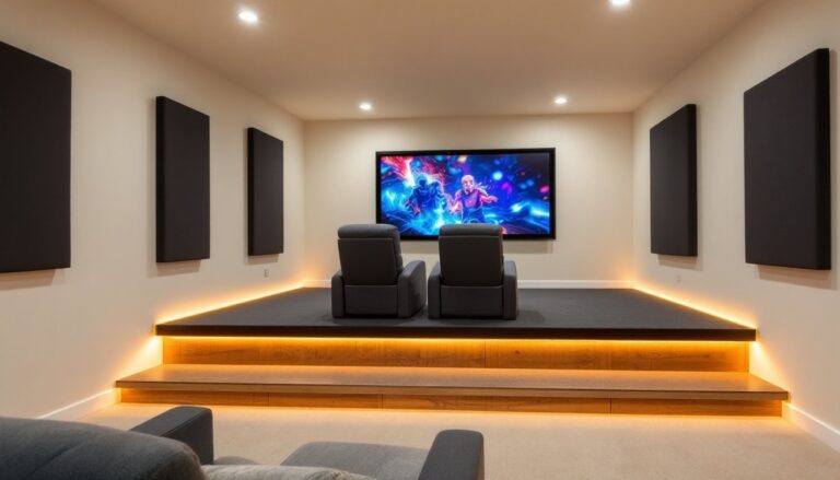
Height speakers for Atmos installations mount in or on the ceiling. Four-speaker layouts (x.x.4) place them slightly forward and behind the seating area, not directly overhead. Ceiling height matters, 8-foot ceilings make Atmos tough: 9-10 feet is ideal. Atmos-enabled upfiring speakers bounce sound off ceilings and work as an alternative to ceiling cuts, though performance suffers with textured or angled ceilings.
Subwoofer placement doesn’t follow the same rules as other speakers. Bass wavelengths are long, 50Hz has a wavelength of about 22 feet, so position matters differently. The “subwoofer crawl” method works: place the sub at the main seating position, play bass-heavy content, then crawl around the room’s perimeter listening for where bass sounds tightest and fullest. Mark that spot on the diagram. Corner loading increases output by 6-9dB but can emphasize room modes (resonant frequencies that cause boom). Dual subwoofers, placed asymmetrically, smooth bass response better than one larger sub.
Creating Your Room Layout Diagram
Start with accurate measurements. Use a laser measuring tool for quick work or a standard 25-foot tape measure. Measure wall-to-wall dimensions at floor level, older homes often have walls that aren’t parallel or square. Note ceiling height in multiple spots: floors and ceilings can slope more than expected.
Draw the room to scale. 1/4-inch scale (1/4 inch equals 1 foot) works well on standard graph paper. Mark permanent fixtures: windows, doors, closets, columns, fireplaces, built-ins. Include electrical outlets, cable/ethernet jacks, and light switches. If there’s attic or crawl space access above or below, note it, that’s the path for running cables.
Add the seating next. Standard theater recliners need 35-40 inches width per seat and 50-60 inches depth when fully reclined. Rows should be 36-42 inches apart, more if there’s no center aisle. Stagger seats in multiple rows so viewers don’t stare at heads in front of them, offset each seat by half a seat width from the row ahead.
Sketch speaker positions using the guidelines from the previous section. Use a protractor or online calculator to verify angles from the main listening position. Draw sight lines from each speaker to the primary seats, if furniture or walls block the path, adjust placement. This comprehensive home theater guide recommends checking clearances for all seating positions, not just the center seat.
Mark the equipment location and screen size. For projectors, draw the throw line from lens to screen and verify there’s mounting structure overhead (ceiling joists, not just drywall). Note screen drop if using a motorized model, it needs clearance to retract into the ceiling or wall.
Wiring and Connection Diagrams Simplified
A wiring diagram runs parallel to the room layout. It shows cable paths, connection types, and lengths. This prevents ordering three HDMI cables when five are needed or buying 50-foot speaker wire spools when 100-foot runs are required.
Start at the AVR and map outbound connections. HDMI runs go to the display and each source (Blu-ray player, game console, streaming box). HDMI 2.1 cables support 4K at 120Hz and eARC: lengths over 15 feet may need active cables or fiber optic models to prevent signal dropout. Don’t run HDMI alongside AC power lines, electromagnetic interference can cause dropouts. Crossing power cables at 90 degrees is fine: running parallel for more than a foot isn’t.
Speaker wire gauge depends on run length and impedance. For 8-ohm speakers, use 16-gauge for runs up to 50 feet, 14-gauge for 50-100 feet, 12-gauge beyond that. Lower gauge (thicker wire) reduces resistance. In-wall speaker wire should be CL2 or CL3 rated for fire safety, jacket markings indicate this. NEC code requires it for any wire run through walls or ceilings.
Label every cable on the diagram. Note source and destination: “HDMI 1: AVR out to TV HDMI 3” or “Front Left: AVR terminal to in-ceiling speaker, 45 feet.” Include connector types, banana plugs, spade terminals, bare wire. This makes troubleshooting easier later and helps if someone else works on the system.
Conduit simplifies future upgrades. Running 1-inch PVC or flexible conduit through walls before finishing lets installers pull new cables later without opening drywall. For systems incorporating advanced surround configurations, pre-installed conduit to ceiling speaker locations is worth the effort.
Network connections matter too. Streaming 4K HDR content needs reliable bandwidth: Wi-Fi works, but gigabit Ethernet from router to AVR or smart TV eliminates buffering. If running Ethernet, use Cat6 or Cat6a cable and terminate to keystone jacks, not direct connections, it’s cleaner and easier to troubleshoot.
Common Setup Mistakes to Avoid
Skipping the diagram entirely ranks first. Installers who “eyeball it” usually end up with speakers at uneven heights, asymmetric angles, or wire runs that fall short by two feet. Measure twice, install once.
Ignoring room acoustics is another frequent miss. Hardwood floors, bare drywall, and large windows create reflections that muddy sound. The diagram should note where acoustic treatment goes: absorption panels at first reflection points (side walls where sound bounces from front speakers to seating), bass traps in corners where low frequencies build up. Not every room needs thousands in treatment, but ignoring it means the system never sounds as good as it could.
Mounting surrounds too low or directly beside ears creates a “speaker in a can” effect instead of immersive sound. They should be 2-3 feet above seated ear height, angled slightly down.
Centering the seating against the back wall seems logical but puts listeners in a bass null or peak caused by room modes. Pull seating 2-3 feet off the back wall for better bass response and to create space for rear speakers in 7.1 layouts.
Undersizing wire paths causes headaches during installation. A single 1/2-inch hole through a stud won’t fit five speaker wires and two HDMI cables. Drill 1-inch holes and use grommet bushings to protect cable jackets from sharp edges. Use a stud finder before drilling, hit a wire or pipe and the project becomes a repair job.
Forgetting about power is common. AVRs, powered subwoofers, displays, and source components all need outlets. Diagram should show dedicated circuits if adding them or map to existing outlets, checking they’re not overloaded. A 15-amp circuit handles roughly 1,800 watts: a large AVR and sub can pull 800-1,000 watts under load.
Tools and Resources for Designing Your Diagram
Graph paper and pencil remain effective for simple rooms. Use 1/4-inch graph paper, a ruler, and a compass for drawing speaker arcs. It’s low-tech but forces careful thinking.
SketchUp Free (web-based) handles more complex layouts. The learning curve is manageable, and the 3D view helps visualize speaker heights and screen positions. Dolby and DTS publish downloadable room templates with proper speaker angles already marked.
Room planning apps like Room Sketcher or Home Designer offer easier interfaces than SketchUp, with furniture libraries for quick layouts. Most have free tiers sufficient for a single-room diagram.
Speaker placement calculators from Dolby, THX, and AVS Forum automate angle math. Input room dimensions and seating position: they output speaker coordinates. Cross-check these against the physical room, calculators assume rectangular rooms with no obstacles.
Laser levels make transferring diagram measurements to walls easier. A self-leveling cross-line laser projects horizontal and vertical references for marking speaker mounts or screen height. Budget models start around $40: they’re worth it for any project involving multiple mounting points.
Cable length calculators prevent ordering short. Measure point-to-point distance on the diagram, add 20% for routing around obstacles and service loops at connections, then round up to the next standard length. Speaker wire sold by the foot allows exact lengths: pre-terminated HDMI cables come in fixed sizes.
Safety note: When drilling into walls or ceilings, wear safety glasses. Use a non-contact voltage tester before drilling to avoid hidden electrical wiring. When working overhead, use a stable stepladder or scaffolding, not a rolling office chair.
Keep the final diagram with the system documentation. Take photos during installation showing wire routing inside walls before closing them up. Future owners (or the installer six months later when something needs changing) will appreciate the record.